PCB Covers for EMI Shielding
01 — What is the problem?
EMI shielding caps create a Faraday cage around components that emit parasitic frequencies on a PCB. While the concept is well known, selecting the right cover type, material, and integration method requires careful consideration of design constraints, maintenance needs, and manufacturing volumes.
02 — Why does it happen?
- Active components on PCBs (processors, oscillators, power converters) radiate electromagnetic energy that can interfere with nearby circuits or fail EMC compliance.
- Board-level shielding is often the most effective way to contain emissions at the source, before they propagate through the enclosure.
- Different PCB layouts and maintenance requirements demand different mounting approaches — soldered covers, clip-on systems, or multi-cavity belts.
- Material selection affects both shielding performance and long-term reliability, especially regarding oxidation resistance after shaping operations.
03 — Consequences
- Unshielded noisy components cause EMI coupling to adjacent circuits, degrading signal integrity.
- Failed EMC certification due to excessive radiated emissions from the PCB.
- Oxidation of tin-plated steel covers after cutting and stamping, reducing ground contact quality over time.
- Difficult maintenance access when single soldered covers are used instead of clip-on designs.
- PCB warping or buckling when grounding and mounting solutions are not properly designed.
04 — Common mistakes
- ✗Using a single soldered cover when the design requires regular maintenance access to shielded components.
- ✗Choosing tin-plated steel without considering that shaping operations (cutting, stamping, bending) damage the tin layer and expose the steel to oxidation.
- ✗Ignoring the mechanical flexibility requirements — covers that are assembled and disassembled repeatedly need alloys with sufficient elasticity.
- ✗Not designing for SMD automation (pick-and-place) when production volumes justify it.
- ✗Using a one-size-fits-all approach instead of custom-designed covers that match the exact PCB layout.
05 — Possible solutions
- ✓Single soldered covers: simplest solution, soldered directly to the PCB — best for permanent installations with no maintenance needs.
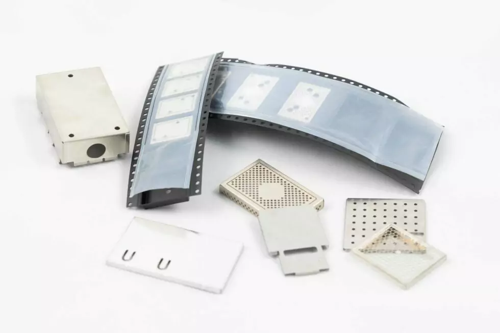
- ✓Clips soldered to PCB: clips are permanently soldered to ground points, and the shielding cover clips on/off — ideal for designs requiring regular maintenance access. Clips also limit PCB buckling.
- ✓EMI shielding belts: soldered frames that accept removable covers — can be designed as multi-cavity structures to shield several component groups with a single belt.
- ✓Material choice — Nickel Silver: offers intrinsic oxidation resistance unlike tin-plated steel, maintaining reliable ground contact even after shaping operations. Alloys are adjusted for the required flexibility and elasticity.
- ✓SMD-compatible design: covers with pick-and-place tips on top, supplied in custom reels or trays for automated placement — essential for high-volume production.
- ✓Custom tooling: most covers are made-to-measure. Soft tooling is available for prototyping and small quantities, while standard tooling supports mass production.
06 — Related topics
07 — Video
Need help on a specific case? Reach out directly: